

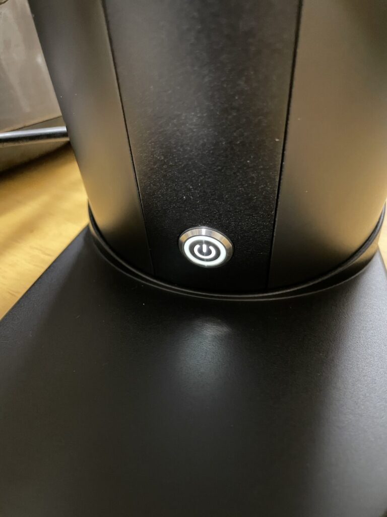
I finally got my DF64 delivered. I immediately plugged it in, pressed the button and… it just did nothing…
OK calm down… I may be doing something stupid. The LED on the switch lights up, so its not completely dead.
So I tried replugging it in. No.
Checked to see that the grind setting wasn’t to fine that the burrs were jamming. No, I can turn the shaft with my hands.
Try flipping it over. No.
Right, it really is dead…
That was pretty devastating. Especially since I had the DF64 imported myself. I was not sure what kind of support I could expect.
But I say “was”, because I did manage to fix the issue. So let me share my experience.
I will cover a way that I used to fix the grinder myself. And I will also share my experience with the customer support of the manufacuter.
What was the issue?
In my case, the DF64’s LED light did turn on when I plugged it in.
But when I press the button, it showed no response what so ever.
Again, the burrs were not locked, and I could spin the motor shaft with my hands.
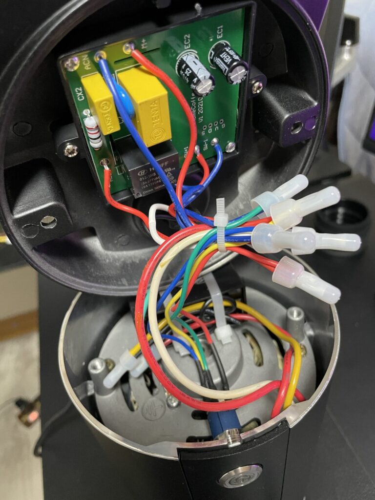
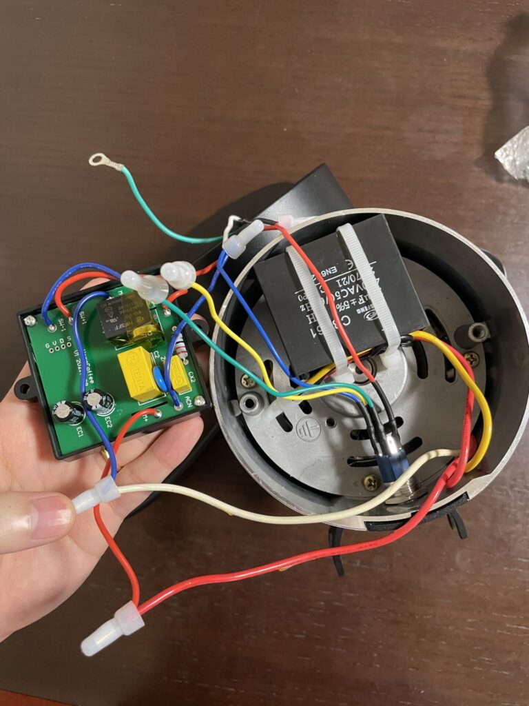
I opened up the grinder and checked the wiring. There were no loose cables, and everything seemed fine.
So immediately reached out to the website I bought the grinder from.
I bought my machine from this website, which I believe is the manufacturers shop. (I just want to note here that their customer support was great! I recommend buying from them if you are trying to import one yourself)
Figuring out the root cause
I emailed the support team, but I couldn’t just do nothing while I waited a few days for a response (since at this point I wasn’t even sure if they would even reply, let alone offer some solution)
Searching online I found this YouTube video. It seemed to explain a very similar situation as my machine.
In this video they said that tapping on the relay will make the motor spin, so I gave it a try.
With the machine filled over, I opened up the bottom plate again and plugged the grinder in.
Press the switch once (this is important), and with the tip of a screw driver, give this black box (the relay) a gentle tap.
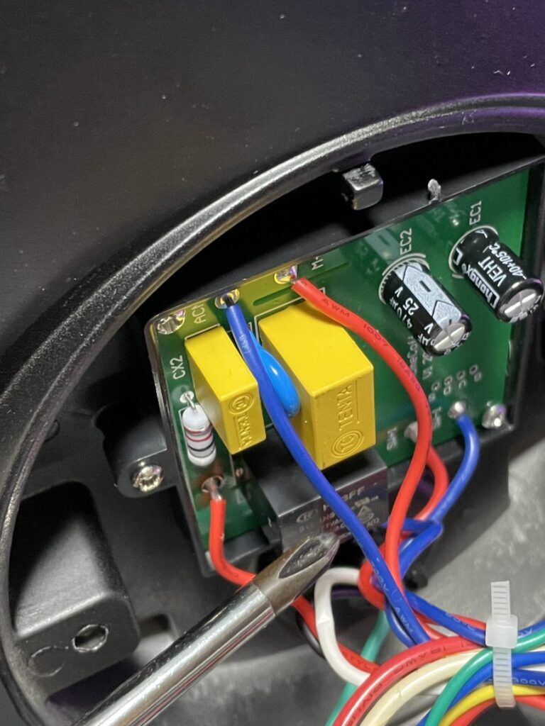
To my delight, the motor started spinning! Awesome, this means that at least the motor is not broken.
Caution! If you would like to try this, please please make sure you do not touch any bare wires. There are places where mains voltage is exposed. If you do not know what you are doing, you should probably not try this.
If you are trying this, make sure you use some insulating gloves, and make absolutely sure you don’t touch any metal parts.
When this trick works, the motor will spin and it will cause the entire grinder to shift. It would be best to not do this on a slippery surface.
Right, so anyway, I figured out where the issue was. The relay is not switching on correctly.
But this isn’t enough to actually fix the grinder, because I would need to keep the grinder upside down and open…
This is as far as the YouTube video went. It just advised to contact your retailer for a circuit board replacement.
This wasn’t quite enough for me, so I kept digging.
A way to fix it yourself
So again, the relay is the issue. How can I fix this without actually getting a circuit board replacement?
I wont go into detail but a relay is a switch which turns ON/OFF electrically using some electromagnets.
If I can getting to work by giving it a tap, my guess was that the electromagnets might be a bit stuck for some reason, and need an extra kick to turn ON.
To give it this extra kick (without actually tapping the relay every time), I used an extra magnet. If I can get it in place to assist the relay to turn ON, this may fix the issue. I tried placing this extra magnet in a bunch of placed around the relay.
And I found that by placing the magnet at the location in the picture, it fixed the issue!
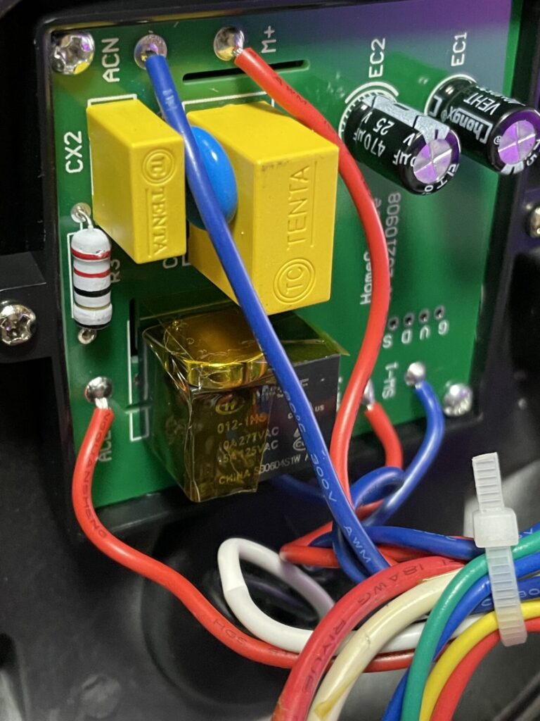
If you are trying to replicate this, make sure you try both sides of the magnet. I am not sure which pole is on which side. And I suggest you use a pretty strong-ish magnet (like neodymium ones)
A note of caution again. When the motor spins, the vibration can dislocate the magnet and worst case short the mains power lines. Make sure to secure the magnet using insulating tape or something. I cannot take responsibility for any damages caused by trying this fix. If you wish to try, attempt at your own risk.
Another thing to note is that while trying multiple locations for the magnet, I found that some locations only worked when the grinder was opened up. When I closed the lid and turned it over to the normal orientation, the issue came back for a lot of magnet locations. I guess since the motor is also a huge magnet, that is affecting the mod.
I would only consider this as a temporary fix. Check with your retailer and ask for a proper fix.
Replacing the circuit board
After a couple of days since sending them an email, I got a reply from customer support.
Apparently this is a known issue that sometimes happens in some parts of Japan.
They told me that a replacement circuit board was already shipped out and on the way. (No extra fees on my end)
I was half expecting no support to be provided, since I imported the grinder to Japan.
But they were great!
By the way, I live in the east side of Japan which uses 100V 50Hz as mains supply. (The west side uses 100V 60Hz, Japan is a strange place)
The specifications of the grinder call for a 100-120V 60Hz supply, so this frequency difference could be the issue, but I don’t know for sure.
The replacement board arrived after a couple of days.
It was really just the board. No instructions, absolutely nothing else. haha.
Luckily, I am an electrical engineer, so I didn’t have any trouble figuring out how to fix it. But I would imagine the same can’t be said for normal users.
To be honest, this board does handle mains power. If you mess up the replacement, it could easily lead to some very nasty injuries.
I would not expect this kind of support form a larger manufacturer.
But for me it worked out nicely, because it would have been a lot more trouble if I had to send the machine back to China to get it fixed.
Replacing the board is not really difficult, so I will leave some instructions for anyone who may have to do this.
First unplug the cable. IMPORTANT
Flip the machine over and open the bottom plate by removing the 2 screws.
The board is bolted on to the bottom plate, so taking these out will make it easier to work with.
You can also unscrew the green wire bolted on to the motor (ground line).
And cut the cable ties bundling the wires together.
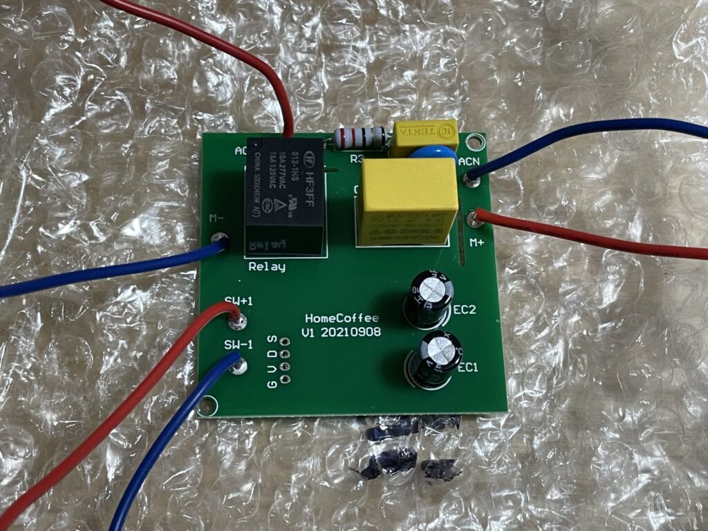
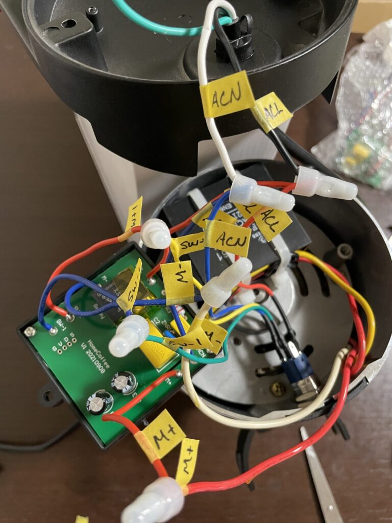
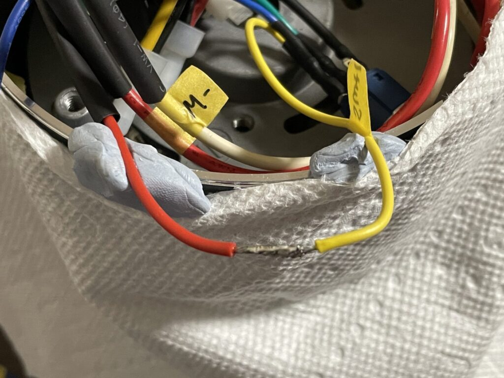
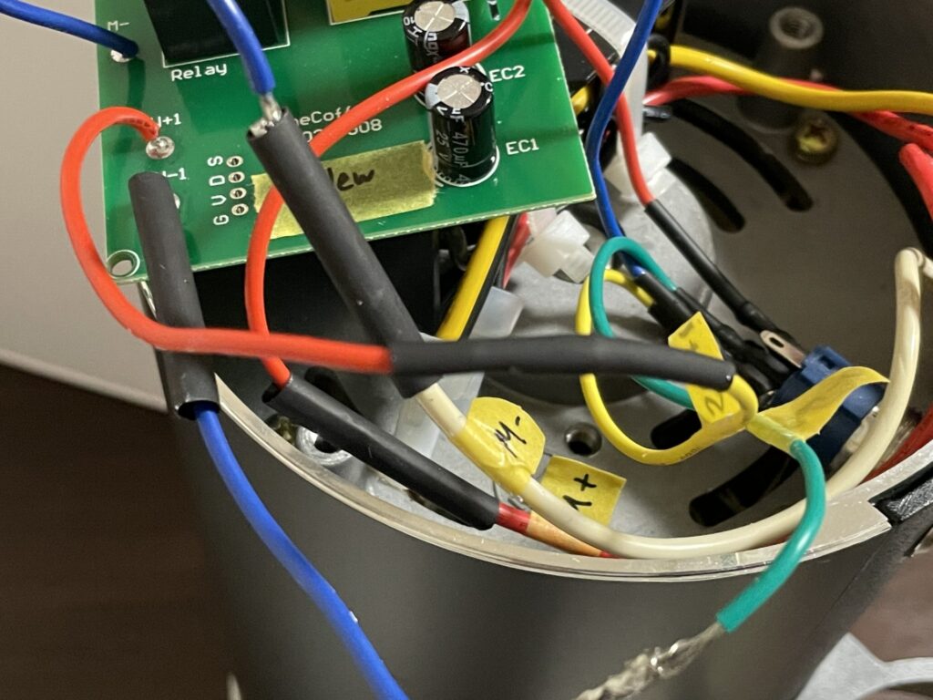
Next, we want to label the wires like this.
The names for the 6 wires are written on the board.
- ACL : AC Power Live
- ACN : AC Power Neutral
- SW+1: Switch
- SW−1:Other side of switch
- M+: Positive side of motor
- Mー:Negative side of motor
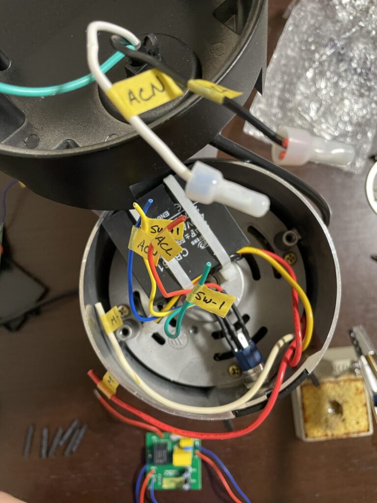
Starting from the board, trace the wires until where it is clamped to another wire (covered in these white covers). Using some tape, label the wires on both side of the clamp. This will tell you which wires to connect together later.
There are 3 wires clamped together for ACL and ACN so don’t forget those.
(Strictly speaking you don’t really need labels on both sides, but it prevents some simple mistakes.)
Once all the wires are labeled, cut the wires on both sides of the clamps.
Next we need to connect the wires to the new board.
I connected the wires using a soldering iron and some heat shrink tubes. (My iron didn’t really get hot enough, so excuse my sloppy soldering…)
If you don’t have a soldering iron (which is probably most of you) then some crimping tools like these may be a bit easier to work with.
You probably can get them from Amazon. And you only have to clamp together the wires.
Finally, once you are done connecting the new board, check for two things
・Are the connections correct? Does the name on the board match the wire labels? Does ACL and ACN have 3 wires?
・Are the connections properly insulated? Please cover and bare wires with some insulating tape.
That’s it! Not too difficult right?
My grinder worked perfectly fine after the replacement!
Summary
I did expect some level of modding to be required for the DF64. After all it’s known for this.
But I didn’t expect that the first thing I would need to do would be to replace the board…
If you happen to be unlucky enough to be in the same spot, I hope this post helped you solve the issue.
Replacing the board might be intimidating for some, but it’s not too hard.
And if it is too much, the temporary fix might work for you better.
I finally can start grinding some coffee with my DF64. I will update you on a must do mod next time.
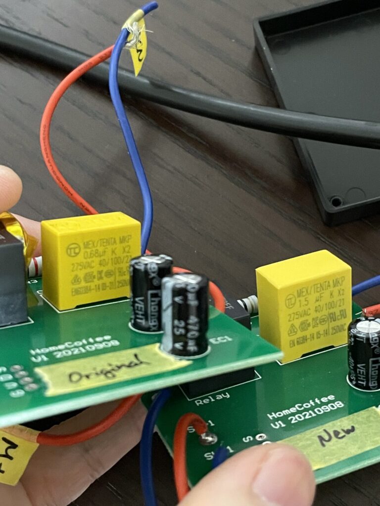
Appendix : Comparing the boards
For those of you electrical engineers who are interested, I will leave a comparison of the boards. (Just because I wanted this info)
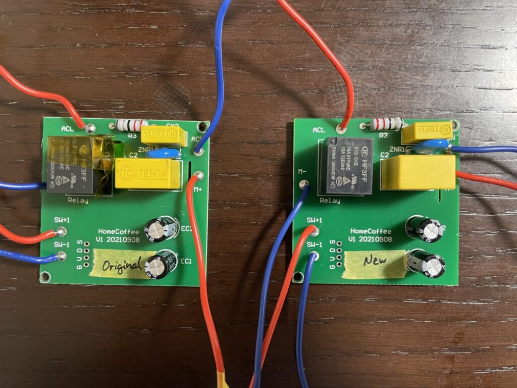
The left board is the original, the right one is the replacement.
They look pretty much identical.
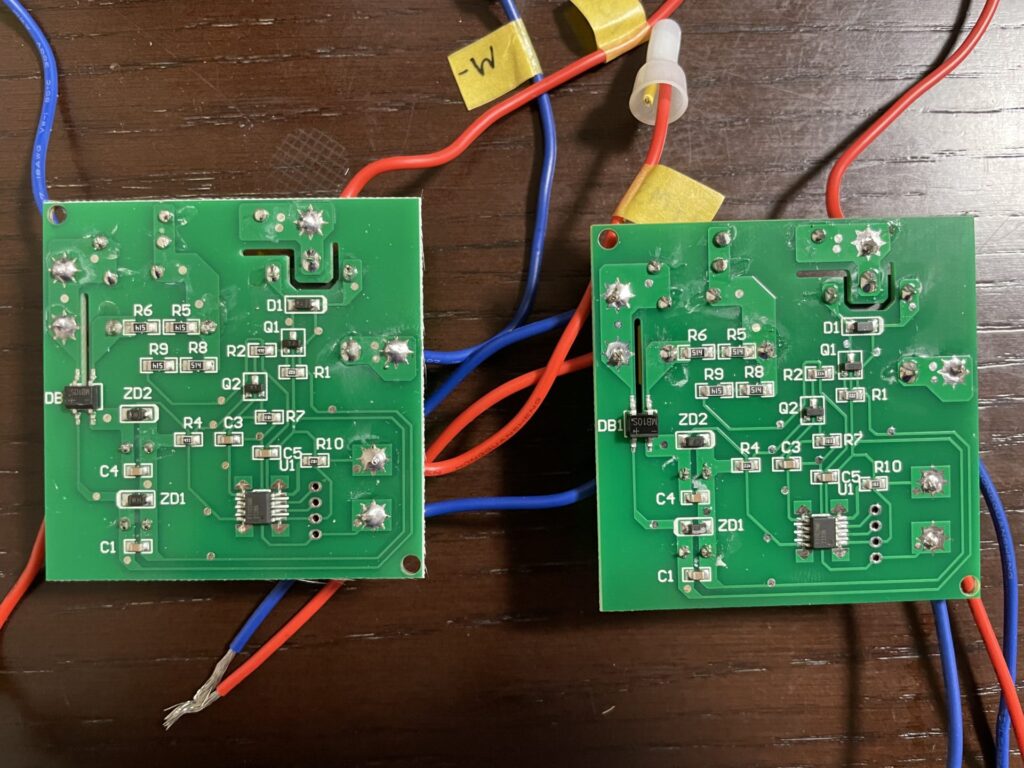
Same for the other side of the board
The only difference I found was the capacitance of this large capacitor.
The original has a 0.68uF, which is replaced by a 1.5uF one.
If I do deeper, I suppose I might be able to find out what this does, but I just had about enough of this, so I will leave it here.
You could try replacing the capacitor yourself, but please note that there may be some other differences that I could not spot.


コメント